Making Parametric Window Families from Point Dloud Data
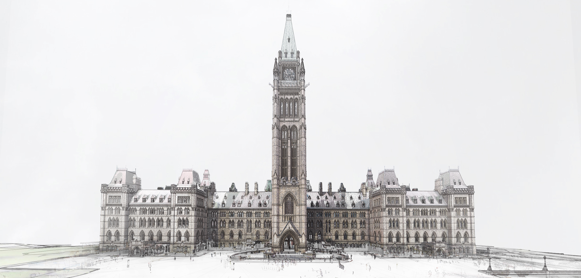
Did you know that the Centre Block of the Canadian Parliament Buildings has over 1000 windows? Of these windows, there are about 100 distinct types; however, NOT ONE of these windows is precisely the same, differing slightly in section or elevation.
All of these slight variations in measurements between windows is captured by Carleton Immersive Media Studio (CIMS) through terrestrial laser scanning. The product of laser scanning is a dense point cloud with millimetre accuracy that CIMS uses to create Building Information Models (BIMs), such as the Centre Block BIM. To ensure the BIM is accurate to the point cloud, the model must capture the small deviations between windows.
How do we capture the differences between each window? We create parametric families in Autodesk Revit for each window type that can be adjusted individually to match point cloud data. A parametric family lets certain dimensions be customized for each instance of a family. That means only one family of a lancet window with intersecting tracery needs to be created to accommodate the multiple slightly different sized ones that may appear in the model.
Want to create a parametric window opening family? The following section highlights the main steps involved when creating a parametric family from point cloud data. To create a window opening family, simply:
Trace the Point Cloud Data
Either in a section view (the easiest method) or elevation view (also works just fine), you can begin to trace geometry of the window opening from point cloud data. Begin by tracing only one side of the opening, then mirror the lines to complete the trace. At this point you can export the lines as a DWG file.

Setup essential Reference Planes
As soon as you have the DWG file loaded into a new Metric Generic Model wall-based family, go ahead and start creating Reference Planes (Ref. Planes) for all rough openings of the window.
Tip: Using Reference Lines (Ref. Lines) for curved geometry will allow for more control when adding Parameters in the next step.

Add Parameters to the Reference Planes
To fully control the window opening, Parameters need to be added to the Revit family. Begin by dimensioning the previous Ref. Planes/Ref. Lines created. Apply Parameters to the dimensions and label them appropriately. Try not to over-constrain the Parameters, to avoid having a hundred errors (but if that happens, or the family becomes overwhelming, feel free to remove some Parameters to get to a manageable family again).

Add Geometry to the Reference Planes
Alright, attention to detail is important with the next step! As you are creating 3D solids or voids from the DWG file – you want to make sure to always align and lock geometry to Ref. Planes and Ref. Lines. This step allows the Revit family to properly expand and contract through the use of Parameters previously created.

__Double check Parameters and Geometry __
It is vital to always check over the family you have created, ensuring Parameters are correctly labelled and functioning, and all geometry is joined correctly to represent the element you have chosen to create. Then import, place, and adjust!

Interested in further expanding your knowledge through a hands-on experience for modelling geometry from point cloud data? Then register today for the From Point-Cloud to Existing Conditions BIM with Revit workshop that the Royal Architectural Institute of Canada (RAIC) is offering this November 17-19 in partnership with CIMS. As part of the workshop, participants will learn the fundamentals of modelling basic geometry and managing a BIM project for heritage and existing conditions buildings.
Looking forward to seeing you soon!